Global message layout
Global message layout
| STX | µC | msg-ID | cmd | cmd-data | CRC | ETX |
|---|---|---|---|---|---|---|
| 1 byte | 1 byte | 1 byte | 1 byte | … bytes | 1 byte | 1 byte |
STX,ETX, escape character
Detecting and differentiating separate messages is done using the STX and ETX.
Implementation can use the following easy rules:
* STX = 0x55
* ETX = 0xAA
* Receive STX -> ignore all previous packet-bytes
* Receive ETX -> packet = all bytes since last STX
* Message = all bytes between last STX and ETX
Each byte in the message can have any binary value.
In order to uniquely identify STX and ETX, we use an escape character on the message-data to prevent STX and ETX from being sent inside the message-data.
Implementation can follow these simple rules:
* Escape char = 0x66
* Encode message-bytes before sending (XOR with escape char):
* Replace message-byte “0x55” by 2 bytes: “0x66 0x33”
* Replace message-byte “0xAA” by 2 bytes: “0x66 0xCC”
* Replace message-byte “0x66” by 2 bytes: “0x66 0x00”
* Decode received message-bytes (XOR with escape char):
replace 2 bytes “0x66 0x??” by 1 byte: “0x66 XOR 0x??”
The STX, ETX and escape-char are chosen to have a minimum of equal consecutive bits. This minimises bit-stuffing in cases where the transport layer makes use of this (like CAN-bus or wireless communication).
µC
Since we can have a setup with more than 1 µC, each message starts with a µC-id which identifies to which µC the message is related.
An id of 0xFF is reserved for accessing all µCs simultaneously. The highest bit identifies the direction:
* bit 7 = 1: PC -> µC
* bit 7 = 0: PC <- µC
Msg-ID
All messages sent from the PC are given a successive msg-ID.
This ID is used to ACK the messages by the slaves.
The slaves ACK each message, by sending at least:
* µC
* msg-ID
* cmd
Msg-ID = 0 is not ACK by the slaves.
This msg-ID can be used by the PC when sending a cmd to all slaves at once.
However, by using a msg-ID != 0 with a global cmd, makes all present µCs ACK the message, which can be a safer route.
Messages sent by the µC are not ACK by the PC, and are therefore sent with msg-ID = 0
Cmd and cmd-data
Each message has a cmd, followed by cmd-data. The cmd identifies the type of message. The amount and type of cmd-data differs per cmd, and can also be 0. The cmds are defined separately.
Command-data may consist of several parameter-values. These may be separated by a ‘record separator’ RS = 0x33. If a record-separator is used, it is described in the command.
Error-checking
Every message has a CRC-check in order to detect transmission failures. The STX and ETX are excluded from the CRC-calculations (if STX or ETX are not received correctly, the message is lost anyway, since we are not able to detect it anyway).
We choose an 8-bit CRC with the following polynomial (CRC-8 Dallas/Maxim):
CRC = x8 + x5 + x4 + x0
If a CRC-check fails, the message is simply discarded. If a message is important, it is indicated in the protocol that the receiver should send a response. If such a response times out at the sender-side, it can be resent. After a multiple or time-outs, the receiver can be indicated as ‘connection lost’.
Debug-channels
Each µC will have 16 so called ‘debug-channels’. A debug-channel is capable of sending a 1-dimensional value (for example a bool, byte, int or double) from the µC to the PC. Each debug-channel can be independently configured through the protocol. This is done by the PC. The PC determines what variable is sent over which channel, and when.
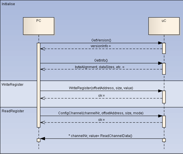
At start-up, we must first initialise/synchronise the debugger softwares on both sides of the communication channel (i.e. embedded sw and pc sw). The following information is exchanged: – version of the debugger software – version of the application software – sizes and byte orientation of the basic types
After that, the pc software can configure and enable/disable debug-channels. The commands use a ‘send-response’ format to ensure safe communication. After enabling, the embedded sw send data as configured without being queried or ack. This one-way sending minimises overhead, leading to maximum throughput. Furthermore, it is assumed that message losses are not critical for debug-data. All this is illustrated by the sequence diagram below.

Byte ordering
Multi-byte values are sent in ‘little endian’ ordering (standard Intel format), i.e. ‘least significant byte’ first. So a 4-byte value 0x12345678 is sent as {0x78, 0x56, 0x34, 0x12}.
In multiple commands a Name is send, this name are send using the UTF-8 encoding.
Encoding
Control byte
The control byte is used in multiple commands, such as writeregister and contains information about the register, e.g. read/write, deref, etc.
bit7…bit4: base-address to use (bit7=read/write, bit6=hand/Simulink, bit4=offset/index):
0000: read hand-written variable, add offset to base-address (‘&theApp’)
0001: read hand-written variable, offset is index of hard-coded variable
0100: read Simulink signal, add offset to Simulink signal base address (‘&g_B’)
0101: read Simulink signal, offset is index of hard-coded Simulink-output
0111: read from to absolute memory-address
1000: write to hand-written variable, add offset to base-address (‘&theApp’)
1001: write to hand-written variable, offset is index of hard-coded variable
1100: write to Simulink-parameter, add offset to parameter base address (‘&g_P’)
1101: write to Simulink-parameter, offset is index of hard-coded Simulink-input
1111: write to absolute memory-address
bit3…bit0: pointer-depth, how deep to dereference the offset-address examples:
0x00: memory-location contains variable value
0x01: memory-location contains single pointer
0x02: memory-location contains double pointer (dereference twice)